| Node 1 | |
|---|---|
| Host: | axel01 |
| CPU: | (Dual CPU) Intel Xeon E5420 @ 2.50GHz |
| RAM: | 16GB DDR2 @ 1066MHz |
| GPU: | nVidia Tesla C1060 |
| FPGA: | Alpha-Data ADM-XRC-5T2 |
| Node 2 | |
|---|---|
| Host: | axel02 |
| CPU: | (Dual CPU) Intel Xeon E5420 @ 2.50GHz |
| RAM: | 12GB DDR2 @ 1066MHz |
| GPU: | nVidia Tesla C1060 |
| FPGA: | Alpha-Data ADM-XRC-5T2 |
| Node 3 ~ 16 | |
|---|---|
| Host: | axel03 ~ axel16 |
| CPU: | AMD PhenomX4 9650 Quad-Core @ 2.30GHz |
| RAM: | 8GB DDR2 @ 1066MHz |
| GPU: | nVidia Tesla C1060 |
| FPGA: | Alpha-Data ADM-XRC-5T2 |
| Node 17 | |
|---|---|
| Host: | axel17 |
| CPU: | AMD PhenomX4 9650 Quad-Core @ 2.30GHz |
| RAM: | 8GB DDR2 @ 1066MHz |
| GPU: | nVidia Tesla C1060 |
| FPGA: | N/A |
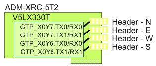
| Host I/F : | PCI/PCI-X |
| FPGA : | Xilinx Virtex-5 LX330T-FFG1738-1 |
| SDRAM : | 1GB DDR-II SDRAM (4 banks x 64M x 32-bits) @ 333MHz |
| SSRAM : | 8MB DDR-II SSRAM (2 banks x 2M x 18-bits) @ 200MHz |
| Ext. I/O : | 8 channel high speed serial link |
In the AXEL cluster, the Xilinx device is host on a carrier card which connected to the host computer with 4X PCIe interface.
The C1060 GPU computing platform from nVidia consisting 240 floating-point capable cores running at 1.296GHz. Double precision floating-point operations are also supported in the hardware. Besides the 4GB DDR3 external memory, large amount of high speed on-chip memory further improve the achievable bandwidth. More information about this accelerator can be found from the vendor's web site.
Tesla C1060 Spec
| # of Streaming Processor Cores | 240 |
| Frequency of processor cores | 1.3 GHz |
| IEEE 754 Single Precision floating point performance (peak) | 933 Gflops |
| IEEE 754 Double Precision floating point performance (peak) | 78 Gflops |
| Total Dedicated Memory | 4 GB GDDR3 |
| Memory Speed | 800MHz |
| Memory Bandwidth | 102 GB/sec |
| System Interface | PCIe x16 |
Connectivities
The major communication channel between compute nodes in the AXEL cluster is a any-to-any Gigabit Ethernet through a Summit X450e-48p Gigabit Ethernet Switch. All nodes connected to the switch through the on-board Ethernet port. A peak of 40Gbps total bandwidth at Layer-4 protocol can be achieved in this channel.
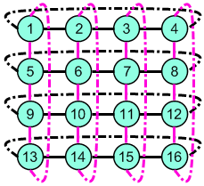
In the AXEL cluster, there is another communication channel which involves FPGA devices only. Each FPGA accelerator has 4 HSSDC2 ports. The 16 nodes in the cluster are arranged into a 4-by-4 grid and 1x-1x Infiniband cables are used to connect the grid into a 2D torus topology. The ports on the FPGA accelerator are labeled as N-E-W-S according to the direction in the torus.
These point-to-point connections facilitate the implementation of a customized low latency communication scheme for large and continues data movement. Although this topology restricts the connectivities of the scheme, the decoupling between the data flow control and CPU involvement make it the ideal interface many applications such as neural network, Lattices-Boltzmann fluid and streaming media.
Cluster Arrangement
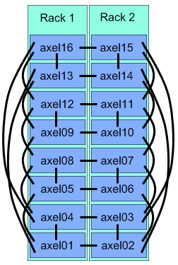 The computed nodes are host in industrial standard 4U chassis. The 16
regular nodes, axel01 ~ axel16, are put together into two 47U racks.
Each rack has its own power sequencer and UPS for system stabilities.
This figure shows the physical location of each node in the rack system
and their interconnections through Infiniband cables.
The computed nodes are host in industrial standard 4U chassis. The 16
regular nodes, axel01 ~ axel16, are put together into two 47U racks.
Each rack has its own power sequencer and UPS for system stabilities.
This figure shows the physical location of each node in the rack system
and their interconnections through Infiniband cables.
The cluster system was supported by two uninterrupted power supply (UPS) units. Each UPS powers 8 nodes in each rack. Besides providing a prolonged run time after power down, the UPS units also provide a steady source for the cluster by filtering sudden spikes. Two power sequencers are also installed to reduce the sudden current changes when all nodes are powered up or power down at the same time.